DaisukeDoyo FabAcademy2018 Circuit Diagram Thermocouples are temperature sensors consisting of two different types of metallic conductors. Thermocouples, mainly used for industrial applications, have the following features compared to other thermometers (such as mercury thermometers and thermistors). Quick response; B-type thermocouple temperature sensors can be used for the highest temperatures. They also provide the most accurate, stable readings in extreme heat conditions. These thermocouples have an optimal temperature range of 0 to 1700 Celsius. Both wires are created from high-quality platinum-rhodium wire the positive consists of 30% platinum and A Basic Guide to Thermocouple Measurements Joseph Wu ABSTRACT Thermocouples are common temperature sensors used in a wide variety of commercial and industrial applications. While slightly less accurate than resistance temperature detectors (RTDs), thermocouples cover a wide temperature range, are self-powered, and have a fast response time.
Infrared Sensors: Infrared thermometers measure surface temperature without contact, but thermocouples provide direct and more reliable readings in varying conditions. RTDs (Resistance Temperature Detectors) : RTDs offer excellent stability and accuracy for specific applications, but thermocouples are more cost-effective and versatile for
PDF A Basic Guide to Thermocouple Measurements (Rev. A) Circuit Diagram
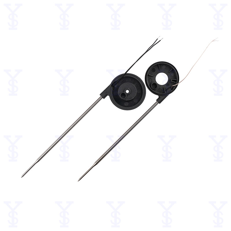
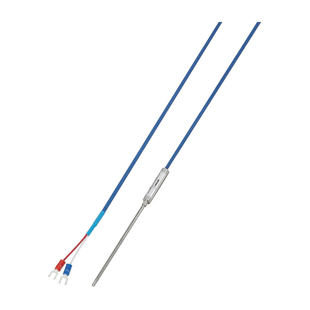
A thermocouple is a simple, robust and cost-effective temperature sensor used in a wide range of temperature measurement processes. Thermocouples are manufactured in a variety of styles, such as thermocouple probes, thermocouple probes with connectors, transition joint thermocouple probes, infrared thermocouples, bare wire thermocouple or even Thermocouple sensors (this article) RTD sensors. Thermistor sensors. Infrared temperature sensors. What is a thermocouple? A thermocouple is a sensor that is used for measuring temperature. The thermocouple is a very popular sensor to its relatively low cost, interchangeability, wide measuring range, and reliability. Using the notation VJx(Ty) to indicate the voltage generated by the junction Jx at temperature Ty, the general thermocouple problem is reduced to the following equation: where V MEAS is the voltage the DAQ board measures, T TC is the temperature of the thermocouple at J1, and T ref is the temperature of the reference junction.
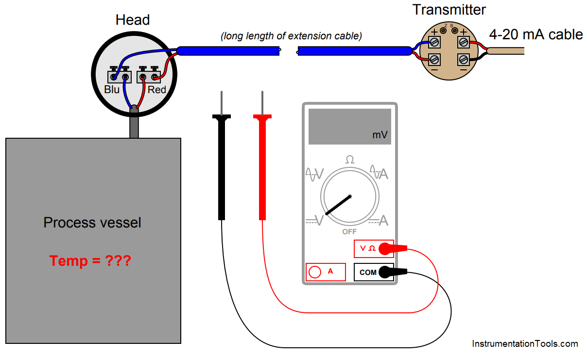
Well a detailed study of the thermocouple will reveal that it is not really a simple device as it seems. From the extension cables that could serve as antenna to pick up stray voltages, to ground loop problems, to advanced signal conditioning modules applied to curb noise and composition challenges in the thermocouple material, it does not appear to be a simple device in the real sense.
How to Use a Thermocouple: Practical Application Tips Circuit Diagram
Temperature measurement is critical in industrial processes, laboratories, and everyday applications. One of the most widely used temperature sensors is the thermocouple.Known for their durability, fast response time, and ability to measure extreme temperatures, thermocouples are widely used in industrial automation, HVAC systems, and scientific research.