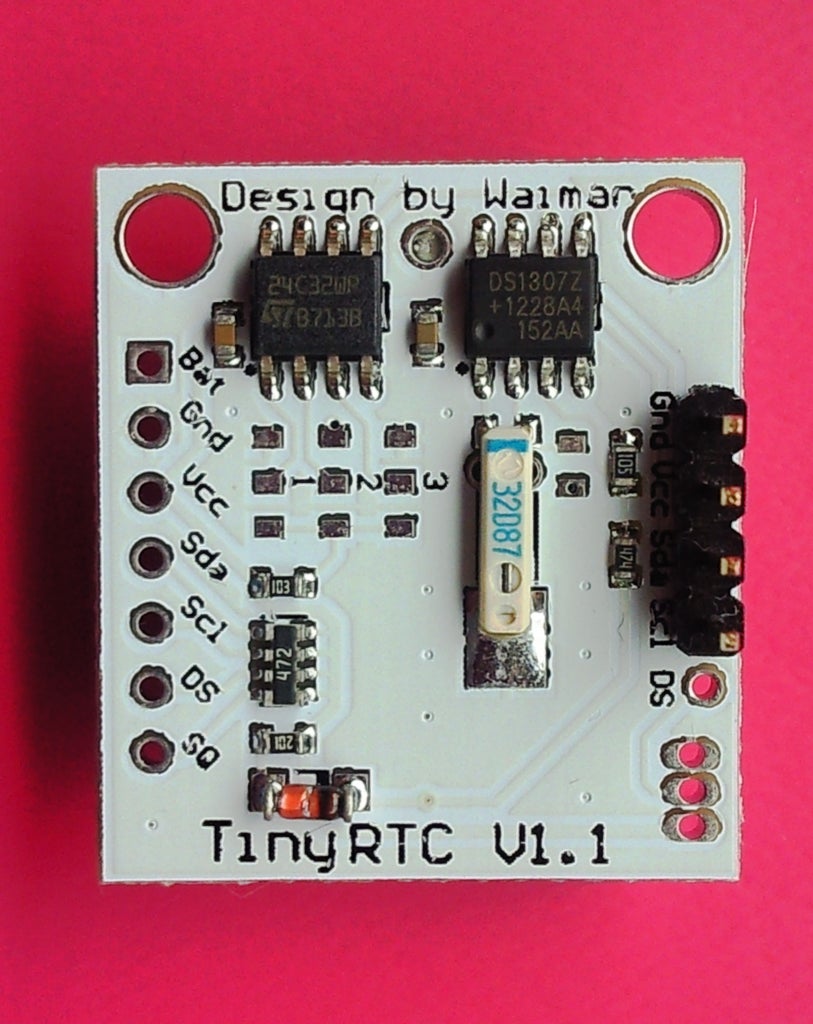
DIY WirelessTemperature Sensor Circuit Diagram Remote Sensor Materials: 10uF 1206 SMD Capacitor. NRF24 Wireless Module. Arduino Nano. BME280 Temp/Humidity Sensor. USB-C Breakout Board. 22AWG Stranded Wire. M3 Screws - Only need 2 M3x8 screws and 3 M3x6. Custom PCB - I got my custom PCBs for this project from PCBWay (my YouTube sponsor), and you can find the files for them on their website
The code helped me quite alot, had to change it a little bit since im using lm35 sensor. I only have one issue, for your code u send humidity and temp, i want to send temp, max and min temp. i tried using ur way with strcat but it only works with if im adding two arrays. hence i can only display temp and max or min. is there a way i could add 3 arrays using strcat. or is there another way The idea of wireless temperature meter can be improved and converted into a complete weather station or it can be used as a low cost WiFi interface to control various devices around your house just by powering up the Arduino based device. The temperature sensor provides output on the center pin, so this pin goes to the A1 (Analog pin) on

NRF24L01 & Arduino Wireless DHT11 Temperature Monitor Circuit Diagram
how to make Wireless Temperature and Humidity Monitoring system by Bluetooth | DHT-22 Temperature and Humidity SensorCode, Schematics and Proteus Simulation
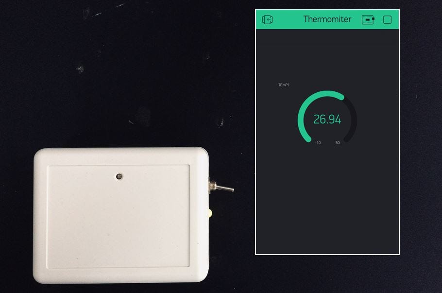
How to make an EASY wireless temperature and humidity monitor with an ESP8266 board and DHT11 Temperature sensor.Buy a DIY kit here:https://store.mkme.org/?p
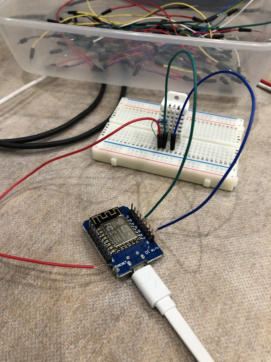
Building a Wireless Temperature Sensor with ESP8266 & Arduino Circuit Diagram
For my first video, I walk through building a wireless temperature sensor based on the ESP8266 chip - the hardware, some theory, and the code.The code used i The DHT11 Temperature and Humidity Module is one of the most commonly used sensors. The DHT11 sensor most frequently is used in Weather Station projects. The DHT11 Temperature and Humidity Sensor has a total of 4 pins. Out of these 4 pins, we will use only three pins. Pin number 3 will not be used. Wireless Temperature monitoring Circuit Diagram: Here we need two circuit assembly to make wireless communication between two NRF24L01 transceiver module. The first circuit diagram shown below is a Transmitter End Section. Assemble the circuit as shown in the figure below. It consists of Arduino Uno, nRF24 & DHT11 Humidity & Temperature Sensor.