EV Motor Controller Circuit Diagram Learn the basics of the electric motor speed controller. In this article we learn how to design a simple PWM speed controller for a DC motor learning how current flows in the circuit and what each component does. You can even build the circuit yourself! Scroll to the bottom to watch the YouTube tutorial.

The Arduino can provide a maximum of 40mA at 5V from its pins. As most motors require more current, the TIP120 transistor acts as a digital switch to control the motor with higher electrical requirements. Ensure that the diode is placed in the correct orientation to prevent back-emf damaging the transistor when the motor turns off.
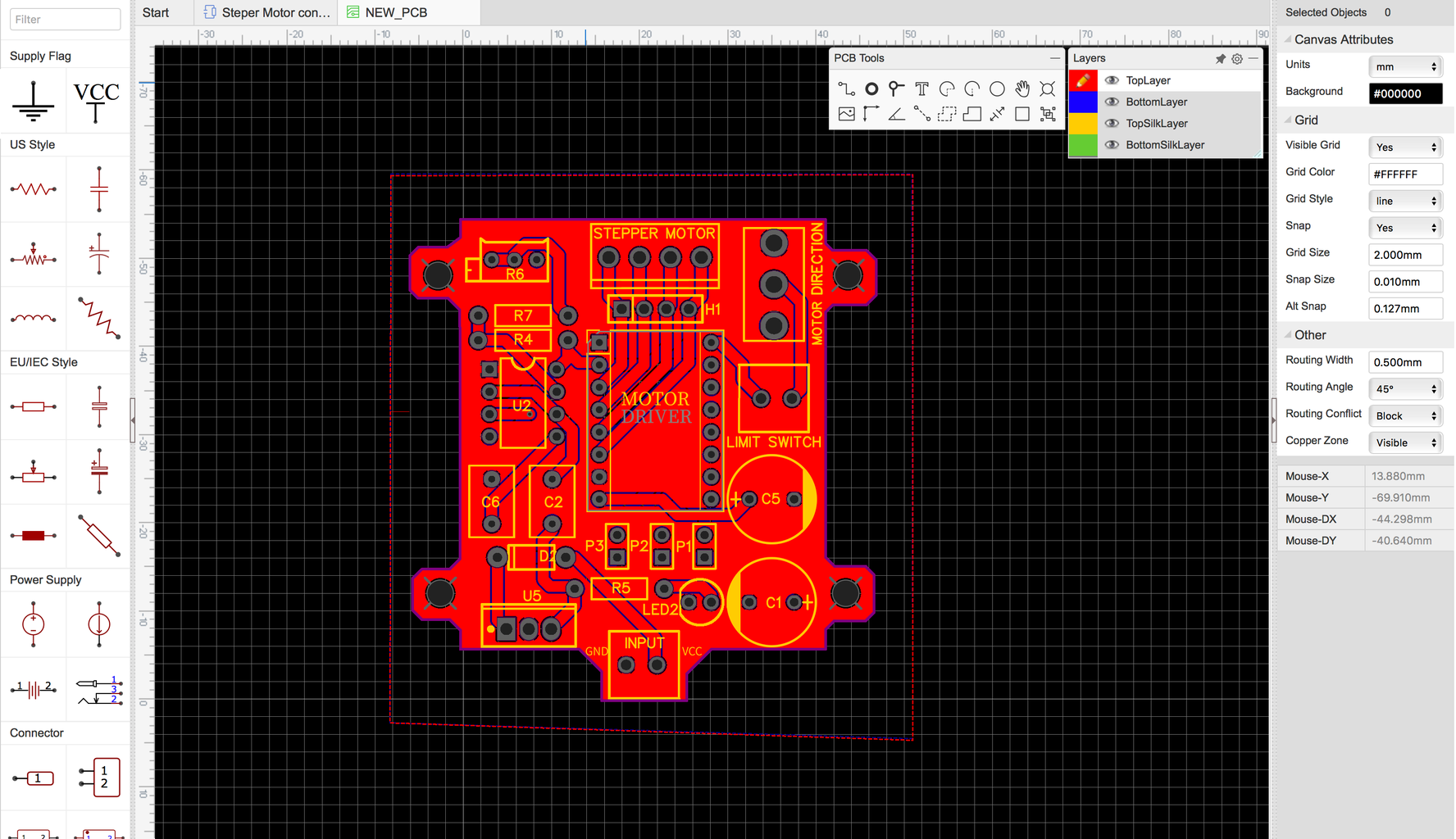
How to Build a High Torque DC Motor Speed Controller Circuit Circuit Diagram
Motor speed controller tutorial - PWM how to buildElectric motor speed controller. In this video we learn how to design a simple PWM speed controller for a D The speed is controlled through an externally applied varying DC voltage source. The most striking feature of this circuit is its ability to provide full torque even at minimum motor speeds. Complete circuit diagram for the motor controller along with the parts list has been included here.

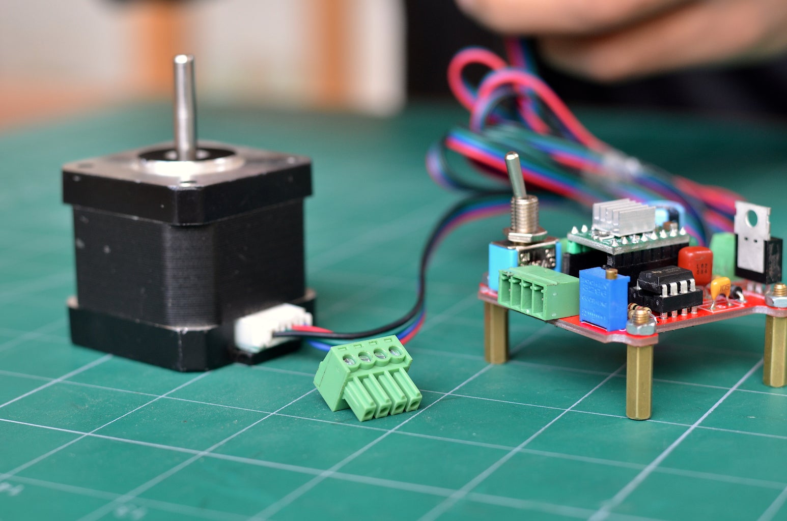
Before powering the circuit check everything for short circuits, faulty wiring and also check for correct input polarity (Vcc & ground). Then power the circuit. If THE MAGIC SMOKE hasn't appeared and the motor is spinning and everything is perfect, then turn the pot shaft to check for the change in speed as you turn it. Do not overload the circuit!

Motor speed controller tutorial Circuit Diagram
Electric motor speed controller. In this video we learn how to design a simple PWM speed controller for a DC motor learning how current flows in the circuit If you have placed your pieces differently or soldered the circuit together differently than just look at the schematics layout above. Either way make sure you look at the schematics diagram above. Setup With a Micro-controller: Plug or connect your motor to the motor pins on your motor controller. Insert the motor controller into a breadboard.